The UK standard for highway structure inspection using DMRB Severity–Extent defect rating and the Bridge Condition Indicator (BCI).
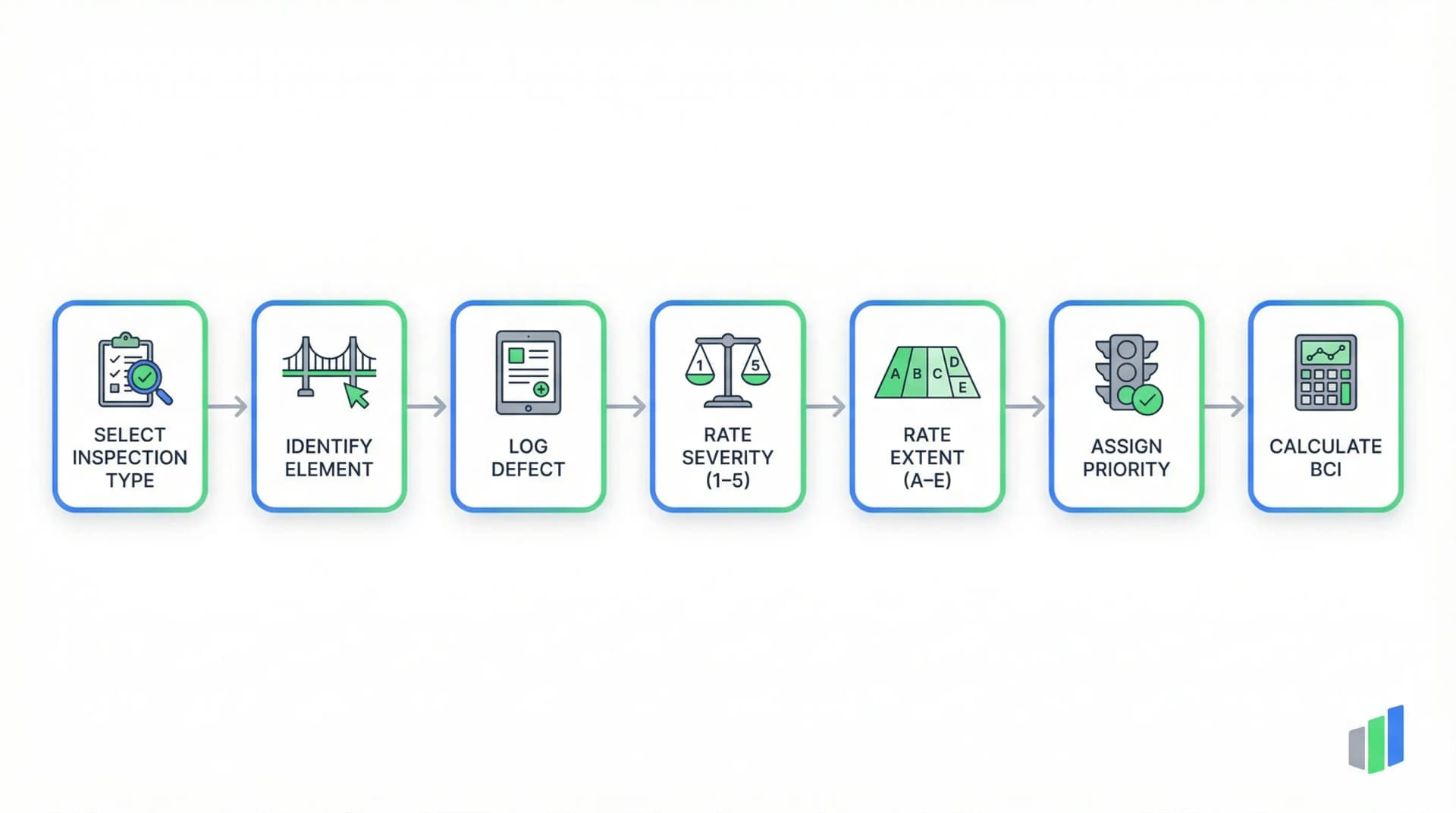
CS 450 is the governing document in the UK Design Manual for Roads and Bridges (DMRB) for the inspection of highway structures — bridges, culverts, retaining walls, and gantries. Working in conjunction with the Inspection Manual for Highway Structures (IMHS), it defines how inspectors decompose a structure into standard elements, log defects with Severity (1–5) and Extent (A–E) scores, assign maintenance priorities, and produce the data that feeds the Bridge Condition Indicator (BCI). This guide covers the four inspection types, the dual-axis rating system, seven element component groups, the defect catalog, and the priority classification used across the UK road network.
What is CS 450?
CS 450 (Inspection of Highway Structures) is the UK DMRB standard for inspecting bridges, culverts, retaining walls, and gantries on the road network. Each defect is rated on two axes — Severity (1–5) and Extent (A–E) — following the Inspection Manual for Highway Structures (IMHS), producing data for the Bridge Condition Indicator (BCI) scores from 0 to 100.
- Full Name
- CS 450 — Inspection of Highway Structures
- Issuing Body
- National Highways (DMRB)
- Current Revision
- CS 450 (formerly BD 63/17)
Four Levels of Structural Inspection Under CS 450
CS 450 defines a hierarchy of inspection types that differ in scope, access requirements, and reporting depth. The inspection type determines how thoroughly each structural element must be examined and what maintenance decisions can follow.
The General Inspection (GI) is the routine visual assessment performed at regular intervals — typically every two years for bridges on the strategic road network. A GI involves a walk-over and drive-past survey covering all visible and safely accessible elements of the structure. The inspector examines the deck surface, parapets, expansion joints, drainage, bearings (where visible from ground level), abutments, piers, and wing walls. The objective is to identify any significant change in condition since the previous inspection: new cracks, progression of existing defects, vegetation encroachment, impact damage, drainage blockages, or settlement. Each finding is logged with a Severity score, Extent score, and photographic evidence. A GI does not require specialist access equipment — the inspector works from ground level, the carriageway, and any accessible footways or verges. However, it cannot assess elements that are hidden, submerged, or only reachable with mechanical access.
The Principal Inspection (PI) is the comprehensive, close-range examination performed at longer intervals — typically every six years. Unlike the GI, a PI requires the inspector to achieve within-arm's-length access to every structural element, including the superstructure underside, bearings, abutment faces, pier shafts, and deck waterproofing. This demands specialist equipment: underbridge inspection units (UBIUs), mobile elevating work platforms (MEWPs), scaffolding, rope access, boats, or increasingly drones with high-resolution cameras. The PI produces the authoritative condition dataset — every element is systematically inspected, all defects are photographed and rated with Severity and Extent scores, and the overall condition of each element is established. The PI report is the primary input for Bridge Condition Indicator calculations, maintenance planning, and structural assessment triggers. Traffic management is almost always required, making PIs significantly more expensive and logistically complex than GIs.
The Special Inspection is triggered by specific events — vehicle strikes, flooding, overloading incidents, structural movement detected by monitoring equipment, or concerns raised during a GI or PI. It can be ordered at any time and focuses on the damage or concern that triggered it, using whatever access methods are necessary to fully assess the affected elements. Special Inspections may involve non-destructive testing (NDT) such as half-cell potential mapping, carbonation depth testing, or chloride content analysis. The Safety Inspection is a rapid assessment focused exclusively on immediate hazards to public safety — loose concrete, unstable parapets, damaged safety fences, or exposed reinforcement over a live carriageway. In the digital form, the inspector selects the inspection type as the first field, which sets the expected scope and mandatory fields for the entire survey.
Inspection standards are maintained by National Highways as part of the Design Manual for Roads and Bridges (DMRB).
The Dual-Axis Defect Rating System (IMHS)
The core of every CS 450 inspection is the per-defect Severity and Extent rating. Unlike single-score systems, the IMHS requires each defect to be evaluated on two independent dimensions — the intensity of the damage and the proportion of the element it affects — producing a risk profile that drives the Bridge Condition Indicator.
Severity measures how advanced or serious the defect is — the degree of deterioration or damage at the worst point. A Severity 1 rating means no significant defect: the element is in as-new condition with no visible deterioration. Severity 2 indicates minor early-stage deterioration — light surface staining, hairline cracks in non-structural elements, or initial paint system breakdown — that does not reduce the element's functionality. Severity 3 marks the threshold where function begins to be affected: moderate cracking with measurable width, spalling that exposes reinforcement cover but not yet the bars themselves, bearing displacement that is visible but within tolerance, or expansion joint seal failure allowing water ingress. This is the critical transition point — defects at Severity 3 typically require planned maintenance intervention.
Severity 4 represents severe damage approaching failure: structural cracks with significant width and depth, extensive spalling with exposed and corroding reinforcement, bearing seizure or tilt beyond tolerance, or parapet deformation from vehicle impact that compromises containment. At Severity 4, the element's function is significantly impaired and failure is plausible in the near term without intervention. Severity 5 means the element has failed or collapsed: the bearing has fractured, the expansion joint has disintegrated, the parapet has been demolished by impact, or the deck section has collapsed. Severity 5 findings trigger immediate safety protocols — lane closures, bridge closures, or emergency propping — because the structure can no longer perform its intended function at that location.
Extent measures the proportion of the element's surface area or length that is affected by the defect. Extent A means no significant defect — matching Severity 1 as the baseline. Extent B (Slight) covers up to 5% of the element — a single localized crack, an isolated spalling patch, or corrosion at one bearing. Extent C (Moderate) covers 5% to 20% — multiple cracks across a beam soffit, spalling at several locations on an abutment face, or corrosion on several parapet rail sections. Extent D (Wide) covers 20% to 50% — widespread cracking across most of a deck soffit, general deterioration of pointing across a masonry arch, or paint system failure across half of a steel girder. Extent E (Extensive) means more than 50% of the element is affected — a complete coating breakdown, full-length cracking, or whole-face spalling. The combination of Severity and Extent is what matters: a Severity 4 defect at Extent B (severe but localized) has a different maintenance implication than a Severity 2 defect at Extent E (minor but everywhere). The BCI algorithm uses both dimensions to calculate the element and structure-level condition scores.
| Score | Label | Description |
|---|---|---|
| 1 | No significant defect | As-new condition. No visible deterioration or damage. |
| 2 | Minor | Early signs of deterioration. No reduction in functionality of the element. |
| 3 | Moderate | Some loss of functionality could be expected. Planned maintenance typically required. |
| 4 | Severe | Significant loss of functionality and/or close to failure. Urgent repair needed. |
| 5 | Failed / Collapsed | Element has failed or collapsed. Functionality is non-existent. Immediate action required. |
Severity definitions are derived from IMHS Table G.10. The score reflects the worst-point condition of the defect, not the average condition across the element.
| Score | Label | Proportion Affected |
|---|---|---|
| A | No significant defect | No measurable area or length affected. |
| B | Slight | Less than 5% of surface area or length. |
| C | Moderate | 5% to 20% of surface area or length. |
| D | Wide | 20% to 50% of surface area or length. |
| E | Extensive | More than 50% of surface area or length. |
Extent definitions are derived from IMHS Table G.7. The percentage refers to the proportion of the individual element (not the whole structure) affected by the specific defect type.
A comparable multi-dimensional defect rating approach is used in the NEN 2767 condition assessment, which uses severity, intensity, and extent as three dimensions. The German DIN 1076 bridge inspection uses a three-axis system (S-V-D) instead of CS 450's two-axis approach.
Try this CS 450 form in Geocadra
We have a pre-built CS 450 inspection template ready to go. Sign up and start your first condition assessment today.
Free 14-day trial. No credit card required.
How Severity and Extent Produce the BCI Score (0–100)
The Bridge Condition Indicator (BCI) is the standardized metric that translates raw Severity–Extent defect data into a single 0-to-100 score for each structure. It is the primary measure used by National Highways and local highway authorities to prioritize bridge maintenance across the UK.
The BCI calculation operates at two levels. BCI Average (BCI_Av) reflects the overall condition of the structure by considering all defects across all elements, weighted by the element's relative importance to the structure's function. A bridge with many minor defects spread across non-critical elements (surfacing wear, light vegetation) may still score a high BCI_Av because the primary structural elements — deck, bearings, substructure — remain in good condition. BCI Critical (BCI_Crit) focuses on the worst-condition element, reflecting the structure's vulnerability at its weakest point. A bridge with excellent overall condition but a single bearing at Severity 4 will have a high BCI_Av but a low BCI_Crit, flagging it for targeted intervention. Both scores range from 0 (worst) to 100 (best), with scores above 80 generally indicating good condition, 65–80 indicating fair condition requiring monitoring, 40–65 indicating poor condition requiring maintenance planning, and below 40 indicating very poor condition requiring urgent attention.
The BCI methodology weights elements by their structural importance. Primary deck elements (beams, slabs) and substructure (abutments, piers) carry the highest weight because their failure would render the bridge unusable or unsafe. Bearings and expansion joints carry moderate weight — their failure is serious but typically allows temporary continued use with restrictions. Parapets carry high weight on the safety dimension because their failure directly endangers road users. Surfacing and drainage carry lower structural weight but can indicate underlying problems when severely deteriorated. The algorithm maps each Severity–Extent combination to a condition factor: Severity 1/Extent A produces a factor of 1.00 (perfect), while Severity 5/Extent E produces 0.00 (complete failure). The element-level scores are then aggregated using the importance weights to produce the structure-level BCI_Av and BCI_Crit values.
In practice, the inspector does not calculate BCI on site — they capture the raw Severity and Extent data for each defect on each element, and the management system computes BCI automatically. However, understanding how the scores work helps inspectors make consistent rating decisions. A common calibration question is: does a hairline crack across 60% of a deck soffit (Severity 2, Extent E) score worse than a 15mm structural crack at one location (Severity 4, Extent B)? The BCI algorithm accounts for both scenarios, but the Severity 4 finding will typically dominate BCI_Crit while the widespread Severity 2 finding affects BCI_Av more. This dual-score approach ensures that both widespread deterioration and localized critical defects are visible to asset managers, preventing either pattern from being masked by the other.
Maintenance Priorities
Based on the Severity–Extent rating and the element's structural role, the inspector assigns a standardized maintenance priority that determines the timeframe for required action.
| Priority | Timeframe | Typical Trigger |
|---|---|---|
| Immediate (Safety Critical) | Within hours/days | Severity 5 finding, or Severity 4 on safety-critical element (parapet, deck). Triggers emergency response protocol. |
| High | Within 1 year | Severity 4 on structural elements, or Severity 3 defects progressing rapidly. Entered into maintenance programme. |
| Medium | By next Principal Inspection | Severity 3 defects stable or slow-progressing. Planned for the next maintenance cycle (up to 6 years). |
| Low (Monitor) | Ongoing observation | Severity 2 defects. Recorded and re-assessed at next GI or PI. No active intervention required. |
Maintenance priority is assigned by the inspector based on engineering judgment. It considers not only the Severity and Extent scores but also the element's structural role, rate of deterioration, and consequences of failure.
Detailed guidance on BCI calculation is available from the CSS Bridge Condition Indicators Guidance Note, published by ADEPT (Association of Directors of Environment, Economy, Planning and Transport).
Structural Element Groups and the Defect Catalog
CS 450 inspections follow a hierarchical decomposition: Structure → Element → Defect. Every defect must be assigned to a specific structural element before it is rated, ensuring traceability from the BCI score back to the physical location on the bridge.
The form captures seven primary element component groups that cover the full structural anatomy of a highway bridge. The Primary Deck Element (Beam/Slab) is the main load-carrying superstructure — reinforced or prestressed concrete beams, steel plate girders, concrete slabs, or masonry arches that span between supports. Defects here receive the highest scrutiny because they directly affect the structure's ability to carry traffic loads. Abutments are the end supports where the bridge meets the embankment, transferring deck loads into the ground. They are exposed to earth pressure, water infiltration, and thermal cycling, making cracking and leakage common findings. Piers and Columns are intermediate supports for multi-span bridges, subject to vehicle impact risk, scour at river crossings, and the full range of environmental exposure.
Bearings are the mechanical devices that transfer loads from the superstructure to the substructure while accommodating movement from thermal expansion, traffic loading, and structural deflection. Seized, corroded, or displaced bearings can introduce unintended forces into the structure — making bearing defects among the most structurally significant findings. Expansion Joints accommodate deck movement at abutments and between spans. When joints fail, water and debris reach the bearings and substructure below, accelerating corrosion and deterioration of the most critical structural elements. Joint condition is therefore a leading indicator of future structural problems. Parapets and Safety Fences are the vehicle restraint and pedestrian containment systems on the bridge edges — their condition directly determines whether the bridge meets current safety standards for vehicle containment level. Surfacing covers the carriageway wearing course and any waterproofing membrane protecting the structural deck beneath.
The defect catalog provides seven standardized defect types that apply across material classes. Spalling indicates concrete cover has broken away, potentially exposing reinforcement to corrosive agents. Corrosion and Rust affects steel components, bearings, reinforcement, and metalwork — scoring high on both severity and long-term durability impact. Cracking is the most common finding, with implications ranging from cosmetic (hairline shrinkage cracks in concrete) to critical (structural fatigue cracks in steel or full-depth fractures in prestressed concrete). Pointing Missing or Defective applies primarily to masonry structures — arches, abutments, and wing walls — where mortar loss allows water ingress and freeze-thaw damage. Leakage and Seepage indicates water penetration through the deck waterproofing or through construction joints, signaling future durability problems for elements below. Vegetation ranges from cosmetic moss growth to destructive root penetration in masonry joints. Impact Damage records vehicle strikes on piers, parapets, soffits, or sign gantries — a common finding on bridges with restricted headroom or narrow clearances.
The complete element list and defect categories are defined in the Inspection Manual for Highway Structures (IMHS). Browse more inspection standards in the standards directory.
Digitize CS 450 Bridge Inspections with Geocadra
CS 450 bridge inspections generate structured defect-level data that must be compatible with highway authority asset management systems. Geocadra replaces paper-based inspection forms with digital workflows purpose-built for DMRB requirements, ensuring every Severity–Extent rating, element classification, and priority assignment is captured consistently.
Repeatable defect logging blocks
Each defect — spalling, corrosion, cracking, leakage, vegetation, impact damage — is captured in a repeatable section with its own element component, location identifier, defect type, Severity (1–5), Extent (A–E), maintenance priority, and photographic evidence. A bridge with twenty defects generates twenty individually rated records, each traceable to a specific element and location.
Dual-axis Severity and Extent enforcement
The form enforces mandatory Severity and Extent scores for every defect entry. The inspector cannot submit a defect without completing both ratings, ensuring the BCI calculation has complete input data. The maintenance priority field captures the inspector's engineering judgment on intervention urgency — from Immediate (Safety Critical) to Low (Monitor).
Seven element component groups with location tracking
Dropdown fields align with the IMHS element classification — Primary Deck, Abutment, Pier/Column, Bearing, Expansion Joint, Parapet/Safety Fence, and Surfacing. A free-text location field captures the specific position (e.g., "North Abutment, East Wing Wall") for precise defect mapping within the structure.
Photo-linked evidence with inspection context
Every defect entry supports photographic documentation with geotagged images linked to the specific record. Context fields capture weather conditions, access methods used (ground level, MEWP, drone, ladder), structure type, and RAMS confirmation — building the complete evidence chain that Principal Inspections require.
Frequently Asked Questions
What is a CS 450 bridge inspection?
CS 450 (Inspection of Highway Structures) is the UK DMRB standard governing how bridges, culverts, retaining walls, and gantries are inspected on the road network. It defines four inspection types — General, Principal, Special, and Safety — and requires each defect to be rated using Severity (1–5) and Extent (A–E) scores that feed the Bridge Condition Indicator.
What is the difference between a General Inspection and a Principal Inspection?
A General Inspection (GI) is a routine visual survey from ground level, performed every two years. A Principal Inspection (PI) requires within-arm's-length access to every element using specialist equipment (MEWPs, underbridge units, rope access), performed every six years. The PI produces the authoritative condition dataset used for BCI calculations and structural assessment.
How does the Bridge Condition Indicator (BCI) work?
The BCI converts raw Severity–Extent defect data into a 0-to-100 score. BCI Average (BCI_Av) reflects overall condition weighted by element importance. BCI Critical (BCI_Crit) reflects the worst-condition element. Scores above 80 indicate good condition, 65–80 fair, 40–65 poor, and below 40 very poor requiring urgent attention.
What do the Severity and Extent scores mean in CS 450?
Severity (1–5) measures the intensity of damage at its worst point — from no defect (1) to failed/collapsed (5). Extent (A–E) measures the proportion of the element affected — from no defect (A) to more than 50% (E). Both scores are assigned independently for each defect and combined to calculate the Bridge Condition Indicator.
What triggers an Immediate (Safety Critical) maintenance priority?
An Immediate priority is assigned when a defect poses a direct risk to public safety — typically a Severity 5 finding (element failed), or a Severity 4 defect on a safety-critical element such as a parapet, deck, or bearing. It triggers emergency response protocols including potential lane closures, bridge closures, or emergency propping.
What structures does CS 450 cover beyond bridges?
CS 450 covers all highway structures on the road network: bridges, culverts (enclosed channels carrying water under roads), retaining walls (structures holding back earth adjacent to the road), and gantries/sign structures. The same Severity–Extent rating system and inspection regime apply to all structure types.
How does CS 450 compare to DIN 1076 for bridge inspection?
Both are national standards for bridge inspection. CS 450 (UK) uses a two-axis Severity (1–5) and Extent (A–E) system producing a BCI score (0–100). DIN 1076 (Germany) uses a three-axis S-V-D system (Stability, Traffic Safety, Durability) producing a Condition Grade (1.0–4.0). Both require hand-close inspection at principal-level and systematic defect documentation.
Digitize your CS 450 inspections
Replace paper forms and spreadsheets with structured digital inspections — built for standards like CS 450.
Free 14-day trial. No credit card required.