The international standard for EV charging station electrical safety inspection and commissioning.
IEC 61851-1 is the foundational standard governing the safety of electric vehicle conductive charging systems worldwide. Together with BS 7671 Section 722 for UK and European installations, it defines the complete verification protocol for Mode 3 AC charging stations — the most common public and commercial EV infrastructure. An IEC 61851 inspection is not a visual walk-around but a rigorous electrical and functional safety assessment: earth continuity, insulation resistance, RCD trip times, and Control Pilot signaling voltages are measured with a Multifunction Tester and an EVSE adapter, then compared against fixed pass/fail thresholds. The inspection covers the full chain from incoming supply through overcurrent protection, earthing system, and each individual charging point.
What is IEC 61851?
IEC 61851 is the international standard for electric vehicle conductive charging systems. It defines safety verification procedures for Mode 3 AC charging stations including electrical tests, Control Pilot protocol validation, RCD protection checks, and visual inspection, producing a Satisfactory or Unsatisfactory result per charging point.
- Full Name
- Electric Vehicle Conductive Charging System — General Requirements
- Issuing Body
- IEC (International Electrotechnical Commission)
- Current Revision
- IEC 61851-1:2017 / BS 7671:2018+A2 Section 722
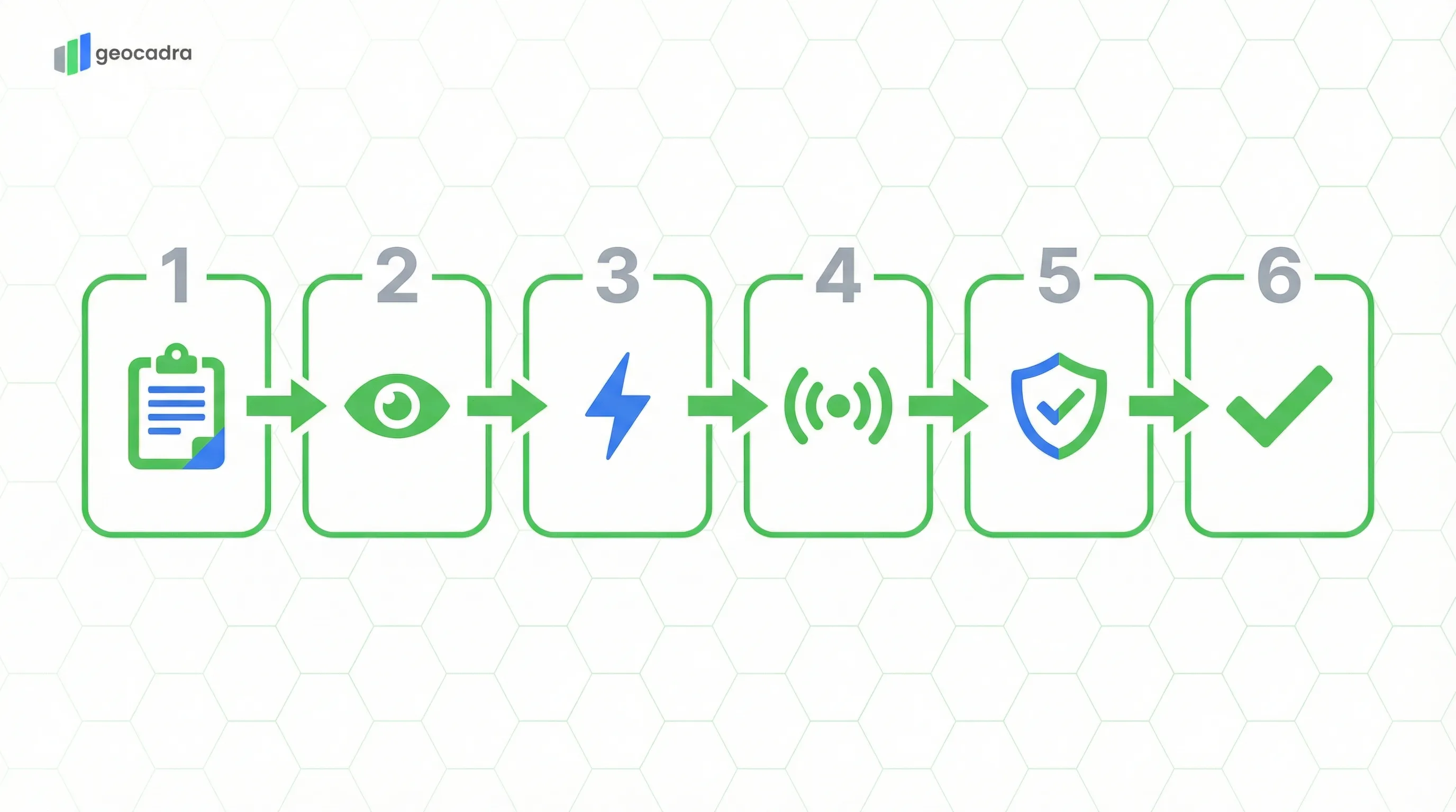
How an IEC 61851 Charging Station Inspection Works
An IEC 61851 inspection follows a structured six-step sequence from station identification through final assessment, using specialized EVSE test equipment.
An IEC 61851 charging station inspection follows a defined sequence that mirrors the logical dependencies between tests. The inspector begins with Station Identification, recording the EVSE ID, manufacturer, model, connector type, rated voltage and current, and — critically — the earthing system of the incoming supply. The earthing system type (TN-S, TN-C-S, TT, or IT) determines which protection methods apply downstream: a TN-C-S (PME) supply, for example, requires additional protective measures such as an earth rod, voltage monitoring, or an Open PEN detection device to mitigate the risk of a lost neutral exposing the charging station enclosure to dangerous voltages.
The second step is the Visual Inspection, covering enclosure condition, IP rating integrity, connector and cable condition, mounting height compliance, ventilation, impact protection barriers, and labelling. Each item receives a Pass, Fail, or N/A classification. Photographic evidence is mandatory — a wide-angle installation photo is always required, and defect photos are captured for any failed items. The visual inspection must be completed before any electrical testing because physical damage can compromise the safety of subsequent live tests.
Steps three through five comprise the Electrical and Functional Testing phase, performed using a Multifunction Tester (MFT) equipped with an EVSE adapter that simulates a connected vehicle. The adapter allows the tester to interact with the charger's Control Pilot circuit without an actual vehicle present. Each charging point on the station is tested individually — a dual-socket pedestal requires the full test suite twice. The final step is the Declaration, where the inspector assigns an overall Satisfactory or Unsatisfactory result, documents any remedial actions required, sets the next inspection date, and signs the report.
Electrical Safety Measurements for EV Charging Points
Each charging point undergoes a battery of electrical measurements that verify the integrity of insulation, earthing, polarity, and overcurrent protection.
IEC 61851 requires four core electrical measurements on every charging point, each with a defined pass/fail threshold. Continuity of the Protective Earth (PE) conductor is tested first, with a maximum acceptable resistance of 0.5 Ohms. This measurement confirms that the protective earthing path from the charging connector back to the main earthing terminal is unbroken and low-impedance — essential because the PE conductor is the primary path for fault current to operate the protective device. In the digital form, the inspector records the PE continuity value in Ohms for each socket.
Insulation Resistance is tested at 500V DC between live conductors and earth. The minimum acceptable reading is 1.0 Megaohms. Values below this threshold indicate degraded insulation that could allow leakage current to flow through the PE conductor, creating a shock risk and potentially preventing the RCD from discriminating between a genuine fault and background leakage. The test must be conducted with the charger isolated from the supply to avoid damage to sensitive electronics inside the EVSE.
Polarity verification confirms that Line and Neutral conductors are correctly connected — a reversed polarity condition would mean the charger's internal switching operates on the neutral rather than the live, leaving energized components in a state that the user might assume is de-energized. Earth Loop Impedance (Zs) is the total impedance of the fault path from the point of test back to the source transformer. The maximum acceptable Zs value depends on the overcurrent protection device rating: a 32A Type B MCB requires Zs below 1.37 Ohms to ensure the device trips within the required disconnection time. The inspector records the Zs value in Ohms and compares it against the threshold for the installed overcurrent device.
| Test | Method | Pass Criteria | Fail Condition |
|---|---|---|---|
| PE Continuity | Low-resistance ohmmeter | <= 0.5 Ohms | > 0.5 Ohms or open circuit |
| Insulation Resistance | 500V DC applied L-E and N-E | >= 1.0 MOhms | < 1.0 MOhms |
| Polarity Check | Phase rotation / polarity tester | L-N correct | Reversed or missing conductor |
| Earth Loop Impedance (Zs) | Loop impedance tester at socket | Below MCB curve threshold | Above threshold for installed device |
Zs maximum values depend on the rating and type of the overcurrent protection device. For a 32A Type B MCB, the maximum Zs is 1.37 Ohms; for a 32A Type C MCB, it is 0.68 Ohms.
Try this IEC 61851 form in Geocadra
We have a pre-built IEC 61851 inspection template ready to go. Sign up and start your first condition assessment today.
Free 14-day trial. No credit card required.
The IEC 61851 Control Pilot Signaling Protocol
The Control Pilot (CP) is the unique communication mechanism of IEC 61851 — a PWM signal on a dedicated pilot wire that negotiates the charging session between vehicle and station.
The Control Pilot (CP) circuit is what makes IEC 61851 fundamentally different from a standard power outlet. It is a dedicated signaling wire between the charging station and the vehicle that carries a 1 kHz PWM (Pulse Width Modulation) signal. The duty cycle of this PWM signal communicates the maximum available current to the vehicle, while the voltage level indicates the current connection state. This handshake protocol ensures that energy is never delivered until both the vehicle and the station have confirmed readiness, and that charging stops immediately if the connection is interrupted.
IEC 61851 defines six Control Pilot states, each corresponding to a specific DC voltage measured on the CP wire. State A (+12V DC) indicates standby — no vehicle is connected and the station is idle. When a vehicle plugs in, the CP voltage drops to State B (+9V PWM), indicating that a vehicle is detected but not yet ready to receive energy. The connector mechanically locks at this point. When the vehicle signals readiness, the voltage drops further to State C (+6V PWM), and the station energizes the power contacts to begin charging. State D (+3V PWM) is rare and indicates ventilation is required — historically for lead-acid batteries in enclosed spaces. State E (0V) signals an error condition with no power available, and State F (-12V) indicates a pilot wire fault.
During inspection, the EVSE adapter simulates a vehicle by presenting the correct resistance values on the CP wire to transition the charger through States A, B, and C. The inspector measures the actual CP voltage at each state and records the values. The form captures CP Voltage State B with a target of 9V and CP Voltage State C with a target of 6V, each with an acceptable tolerance of plus or minus 1V. A charger that produces 7.5V in State B or 4.8V in State C has a degraded pilot circuit that could cause intermittent charging failures or prevent vehicles from initiating a session. The Mechanical Interlock Check confirms that the connector locks when entering State B — a failed interlock means the cable can be removed under load, creating an arc flash hazard.
| State | Voltage | Condition | Action |
|---|---|---|---|
| A (Standby) | +12V DC | No vehicle connected | Station idle, no energy |
| B (Vehicle Detected) | +9V PWM | Vehicle plugged in, not ready | Connector locks, no energy |
| C (Charging) | +6V PWM | Vehicle ready to charge | Power contacts energized |
| D (Ventilation) | +3V PWM | Charging with ventilation required | Rare — lead-acid batteries |
| E (Error) | 0V | No power available | Fault condition, station off |
| F (Fault) | -12V | Pilot wire error | Station shuts down |
All voltage values have a tolerance of plus or minus 1V. The PWM duty cycle in States B, C, and D communicates the maximum available charging current to the vehicle.
Earthing Systems and Residual Current Protection
The earthing system and RCD configuration are the most critical safety factors in an EV charging installation, with specific requirements that differ from standard socket circuits.
EV charging installations have stricter earthing and RCD requirements than standard domestic socket outlets because the vehicle's conductive chassis is directly connected to the protective earth conductor during charging. A fault on the supply side — particularly a lost neutral in a TN-C-S (PME) system — could elevate the PE conductor to a dangerous voltage, which would then be transferred directly to the vehicle body. This is why BS 7671 Section 722.411.4.1 mandates additional protective measures for TN-C-S supplies: an earth rod providing an independent earth path, continuous voltage monitoring that disconnects the supply if the neutral is lost, or an Open PEN detection device. In the inspection form, the inspector first selects the Earthing System from four options (TN-S, TN-C-S, TT, IT), and if TN-C-S is selected, the PME Protection Method field becomes active with options for Earth Rod, Voltage Monitoring, and Open PEN Detection Device.
RCD (Residual Current Device) protection for EV charging is uniquely demanding because electric vehicles can generate DC fault currents that blind conventional Type AC and Type A RCDs. IEC 61851 and BS 7671 require either a Type B RCD (which detects AC, pulsating DC, and smooth DC fault currents) or a combination of a Type A RCD with an RDC-DD (Residual Direct Current Detection Device) that trips at 6 mA DC. The RDC-DD is often integrated into the EVSE itself rather than installed as a separate device in the distribution board. During inspection, the RCD trip time is measured at both 1x rated residual current (maximum 300 ms) and optionally at 5x rated residual current (maximum 40 ms). The RDC-DD is tested separately with a 6 mA DC test current.
The interaction between the earthing system and RCD configuration creates several inspection scenarios. A TT earthing system with a Type B RCD is the simplest compliant configuration. A TN-C-S system with an earth rod and Type A RCD plus integrated RDC-DD is the most common UK installation. A TN-S system requires no additional PME protection measures but still needs DC fault current detection. The inspector must verify not just that the individual components are present, but that the combination is correct for the earthing system in use.
Detailed RCD requirements for EV charging installations are specified in BS 7671 Section 722 (IET Wiring Regulations).
Physical Condition and Compliance Checks
The visual inspection verifies the physical integrity, signage, and siting requirements of the charging station before any electrical tests are performed.
The visual inspection phase of an IEC 61851 assessment covers the physical condition of the EVSE enclosure and its immediate environment. The Enclosure Condition check verifies that the housing has no cracks, UV degradation, or impact damage that could compromise the IP (Ingress Protection) rating. A charging station installed outdoors must maintain at least IP44 protection — meaning it is protected against solid objects larger than 1 mm and splashing water from any direction. Any visible gap in the enclosure sealing, a missing gasket, or a cracked cover panel results in a Fail for this item.
Impact Protection assesses whether physical barriers such as bollards or wheel stops are present where the charging station is at risk of vehicle impact. A wall-mounted unit in a parking bay without a kerb or bollard between the parking space and the charger is a common failure point. Labelling and Signage verification confirms that all required markings are present and legible: the EVSE identification number, electrical warning labels, emergency contact information, and operating instructions. Faded or missing labels are classified as a fail even if the station is otherwise functional, because they represent an information safety hazard in emergency situations.
For every visual inspection, photographic documentation is mandatory. The inspector captures a wide-angle photo showing the complete installation in context — the charging station, its mounting, surrounding barriers, and approach path. If any visual check results in a Fail, additional close-up photos of the defect are required. These photos become part of the permanent inspection record and serve as evidence for remediation tracking. All standards inspection pages are listed in the standards library.
Mounting height requirements and siting guidance are detailed in the IET Code of Practice for EV Charging (4th Edition).
Frequently Asked Questions
What is IEC 61851?
IEC 61851 is the international standard for electric vehicle conductive charging systems. It defines the general requirements for Mode 1 through Mode 4 charging, including the Control Pilot signaling protocol, safety interlocks, and connector specifications. Most public AC charging stations operate under Mode 3 as defined by IEC 61851-1.
What equipment is needed for an IEC 61851 inspection?
An IEC 61851 inspection requires a Multifunction Tester (MFT) for electrical measurements and an EVSE adapter that simulates a connected vehicle. The adapter presents the correct resistance values on the Control Pilot and Proximity Pilot wires, allowing the tester to verify CP voltage states and trigger the charging sequence without a real vehicle.
How often should EV charging stations be inspected?
BS 7671 does not prescribe a fixed interval, but the IET Code of Practice for Electric Vehicle Charging recommends periodic inspection every 12 months for commercial and public installations, and every 5 years for domestic installations. High-usage public stations may warrant more frequent inspection intervals.
What is the difference between Type A and Type B RCDs for EV charging?
A Type A RCD detects AC and pulsating DC fault currents but cannot detect smooth DC faults. A Type B RCD detects AC, pulsating DC, and smooth DC faults. EV chargers can produce DC fault currents, so either a Type B RCD or a Type A RCD combined with a 6 mA RDC-DD device is required.
What are the Control Pilot states in IEC 61851?
IEC 61851 defines six Control Pilot states: State A (12V, standby), State B (9V, vehicle detected), State C (6V, charging), State D (3V, ventilation required), State E (0V, error), and State F (-12V, fault). The inspector verifies voltages at States B and C during the functional test.
Why does a TN-C-S (PME) supply need extra protection for EV charging?
In a TN-C-S system, a lost neutral (broken PEN conductor) can elevate the protective earth to mains voltage. Since the vehicle chassis is connected to PE during charging, this would make the entire vehicle body live. BS 7671 Section 722 requires additional measures such as an earth rod or Open PEN detection device.
What is the difference between IEC 61851 and IEC 62196?
IEC 61851 defines the charging system requirements including signaling protocols, safety interlocks, and operational modes. IEC 62196 defines the physical connector and plug specifications — the shape, pin layout, and mechanical properties of Type 1, Type 2, and CCS connectors. They are complementary standards used together.
Digitize your IEC 61851 inspections
Replace paper forms and spreadsheets with structured digital inspections — built for standards like IEC 61851.
Free 14-day trial. No credit card required.