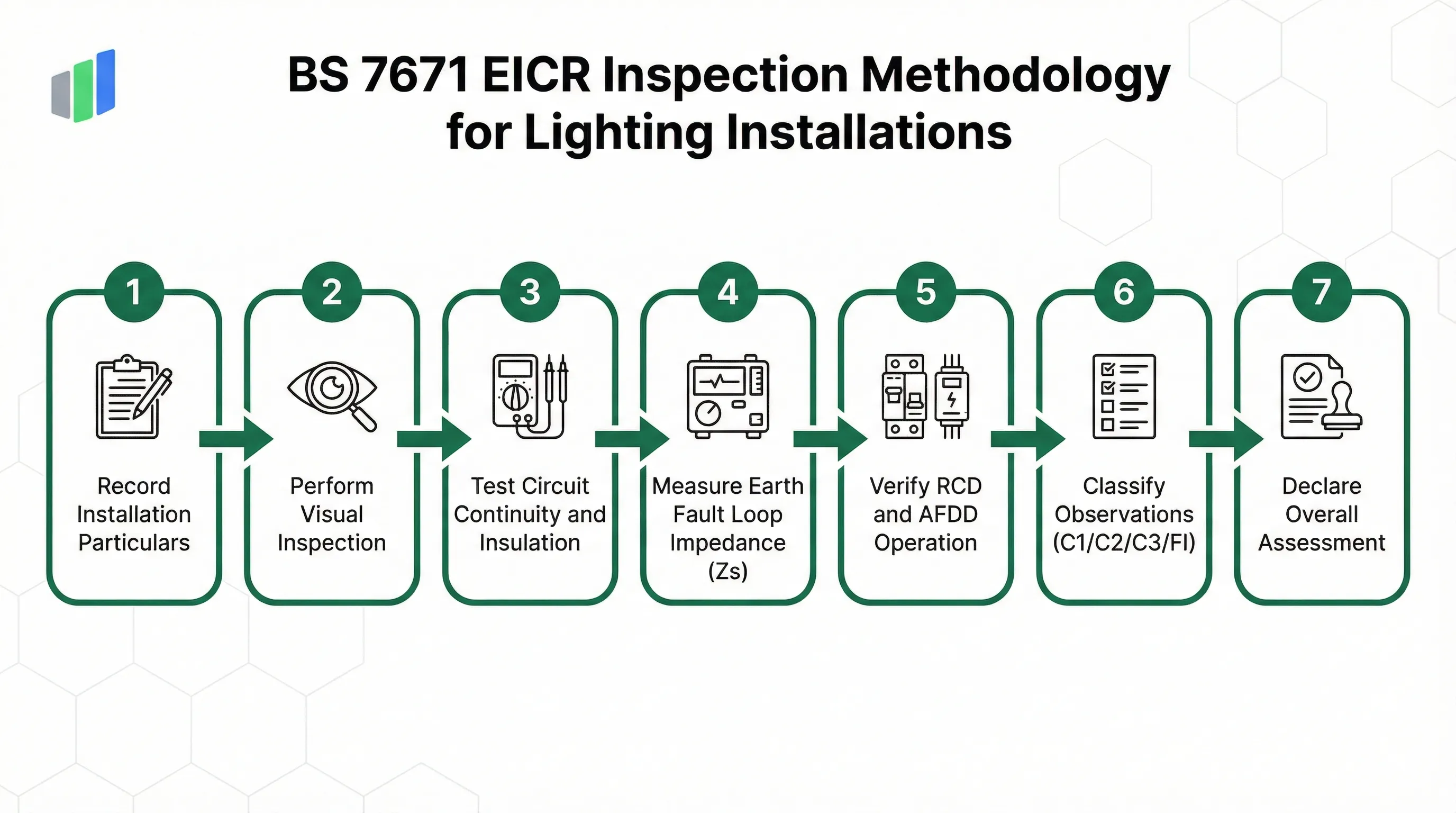
The UK standard for inspecting and certifying the safety of electrical wiring installations in lighting circuits.
BS 7671:2018+A2:2022, commonly known as the IET Wiring Regulations (18th Edition with Amendment 2), is the definitive UK standard governing the design, installation, and inspection of electrical systems. The Electrical Installation Condition Report (EICR) is the formal inspection instrument used to assess existing electrical installations for continued safe use. Unlike the Electrical Installation Certificate (EIC) issued for new work, the EICR focuses on identifying deterioration, damage, defects, and non-compliances in aging installations. For lighting circuits specifically, inspectors verify earthing arrangements, protection device suitability, insulation resistance, earth fault loop impedance, and RCD operation. Every observation is classified using the C1, C2, C3, and FI coding system, which drives the overall Satisfactory or Unsatisfactory assessment and determines whether immediate remedial action is required.
What is BS 7671?
BS 7671:2018+A2:2022 (IET Wiring Regulations, 18th Edition) is the UK national standard for electrical installation safety. The Electrical Installation Condition Report (EICR) assesses existing lighting and power circuits through visual inspection, instrument testing, and defect classification using C1, C2, C3, and FI observation codes.
- Full Name
- Requirements for Electrical Installations — IET Wiring Regulations (18th Edition, Amendment 2)
- Issuing Body
- IET (Institution of Engineering and Technology) / BSI
- Current Revision
- BS 7671:2018+A2:2022
Recording Installation Particulars and Supply Characteristics
Every EICR begins by documenting the fixed attributes of the electrical supply, earthing system, and main protective bonding to establish the baseline for all subsequent tests.
The first section of a BS 7671 Electrical Installation Condition Report captures the installation particulars and supply characteristics that define the electrical environment being assessed. The Reason for Report field records the purpose of the inspection, which may range from a landlord safety check required under the Electrical Safety Standards in the Private Rented Sector (England) Regulations 2020 to a change-of-occupancy assessment or periodic maintenance review. The Estimated Age of Wiring provides critical context for the inspector. Wiring systems installed before the widespread adoption of PVC/PVC cables and modern RCD protection carry inherently higher risk profiles and typically require more detailed scrutiny during the visual inspection phase.
The Earthing Arrangement field is one of the most significant entries in the entire report. BS 7671 recognizes four earthing system types: TN-C-S (also known as PME or Protective Multiple Earthing), TN-S (separate neutral and earth conductors from the supply), TT (where the installation provides its own earth electrode), and IT (isolated terra, used in specialized applications). The earthing type directly determines the maximum permitted disconnection times, the required earth fault loop impedance values, and whether additional RCD protection is mandatory. For example, TT systems always require RCD protection because the earth fault loop impedance is typically too high for overcurrent devices alone to provide disconnection within the required time.
The External Earth Fault Loop Impedance (Ze) is measured at the origin of the installation and represents the impedance of the supply earth path back to the transformer. This value, combined with the circuit conductor resistance (R1+R2), produces the total earth fault loop impedance (Zs) for each circuit. If Zs exceeds the maximum permitted value for the protective device, the circuit cannot guarantee disconnection within 0.4 seconds for final circuits or 5 seconds for distribution circuits, making additional protection essential. The Main Bonding fields confirm whether equipotential bonding conductors are connected to metallic service pipes for water, gas, and structural steel, preventing dangerous potential differences between simultaneously accessible conductive parts.
For outdoor lighting column inspections that also reference BS 7671 earthing requirements, see the ILP GN22 ATOMS standard.
Schedule of Inspections: The Visual Checklist
Before any instruments are connected, the inspector performs a comprehensive visual survey covering six inspection groups that mirror the physical layout of the installation.
The Schedule of Inspections is a structured visual checklist defined in BS 7671 Appendix 6. Each item receives a classification of Satisfactory, Unsatisfactory, Not Applicable, or Limitation (LIM). An Unsatisfactory mark triggers a mandatory observation entry in Section 4, ensuring that every visual deficiency is formally documented with a classification code. The six inspection groups in the digital form cover the complete path of electrical energy from supply intake to final accessories.
Intake Equipment covers the condition of the service cable, service head, meter, and isolator where the supply enters the building. Protection Methods assess whether basic protection (insulation of live parts, barriers, enclosures) and fault protection (automatic disconnection of supply) are adequate. Critically, this group now includes verification of additional protection through 30mA RCDs for all socket outlets rated up to 32A and for cables concealed in walls at a depth of less than 50mm, regardless of whether they are protected by an RCD at the distribution board. Distribution Equipment examines the consumer unit or distribution board itself, including working space adequacy, enclosure condition, IP rating suitability, presence of circuit charts, and correct labelling of protective devices.
The Circuits and Cables group verifies conductor identification, cable support adequacy, and physical condition. Inspectors look for signs of mechanical damage, thermal degradation from overloading, and cable routes that violate safe zones defined in BS 7671 Section 522. The Accessories group covers switches, socket outlets, and lighting points for damage, correct polarity, and secure fixings. Finally, the Special Locations group addresses areas with increased risk such as bathrooms and shower rooms, where zone compliance under BS 7671 Section 701 must be verified, and outdoor lighting installations where IP ratings and UV resistance become relevant factors.
For accessibility-focused electrical outlet inspections in buildings, the DIN 18040 Accessibility standard provides complementary guidance.
Circuit Details and Instrument Test Results
Each circuit in the installation is individually tested, recording protection device characteristics, conductor specifications, and measured electrical values.
The Schedule of Circuit Details and Test Results is the most technically intensive section of the EICR. For every circuit, the inspector records the Circuit Reference, a Description (such as "Ground Floor Lights" or "Kitchen Ring"), the Overcurrent Protective Device (OCPD) type and rating, and the conductor cross-sectional area. BS 7671 recognizes four main OCPD types relevant to lighting circuits: MCB Type B (standard tripping curve for resistive and lighting loads), MCB Type C (higher inrush tolerance for inductive loads), BS88 Fuses (high-rupturing-capacity cartridge fuses), and RCBOs (combined overcurrent and residual current protection in a single device). The conductor CSA for lighting circuits in domestic installations is typically 1.0 mm² or 1.5 mm², though larger sizes may be found in commercial or industrial installations.
The instrument testing regime produces several critical measurements. The R1+R2 continuity test measures the combined resistance of the line conductor and circuit protective conductor from the distribution board to the furthest point. This value, added to Ze, gives the total earth fault loop impedance Zs for that circuit. The maximum permitted Zs depends on the OCPD type and rating. For a 6A Type B MCB, BS 7671 Table 41.3 specifies a maximum Zs of 7.67 ohms at ambient temperature, reduced to approximately 6.13 ohms to allow for conductor temperature rise during fault conditions. If the measured Zs exceeds the corrected maximum, the circuit fails and must be classified as at least C2 (Potentially Dangerous).
Insulation Resistance (IR) is measured between live conductors and earth using a 500V DC test instrument. The minimum acceptable value for circuits up to 500V is 1.0 megohm, though readings above 2 megohms are expected for healthy installations. A reading below 1.0 megohm indicates insulation breakdown and potential current leakage that could cause electric shock or fire. The RCD Trip Time test verifies that any residual current device protecting the circuit operates within 300 milliseconds at its rated residual current. For 30mA RCDs providing additional protection, the trip time at rated current must not exceed 300ms and at five times rated current must not exceed 40ms. The AFDD Status field, introduced with Amendment 2, records whether an Arc Fault Detection Device is fitted and operational.
Try this BS 7671 form in Geocadra
We have a pre-built BS 7671 inspection template ready to go. Sign up and start your first condition assessment today.
Free 14-day trial. No credit card required.
Observation Classification: The C1, C2, C3, and FI System
Every defect discovered during inspection and testing is classified using a four-code system that determines the urgency of remedial action and directly controls the overall assessment outcome.
The BS 7671 observation classification system is the mechanism that translates individual inspection findings into actionable outcomes. Unlike scored condition assessment standards that produce a numerical grade, BS 7671 uses a categorical coding system where the most severe code found in any single observation drives the entire report outcome. A single C1 observation makes the entire installation Unsatisfactory regardless of how many other items are Satisfactory. This binary logic reflects the safety-critical nature of electrical installations, where one defect can present an immediate danger to life.
| Code | Classification | Action Required | Report Impact |
|---|---|---|---|
| C1 | Danger Present | Immediate remedial action required; person ordering report must be informed at once | UNSATISFACTORY |
| C2 | Potentially Dangerous | Urgent remedial action required | UNSATISFACTORY |
| FI | Further Investigation | Further investigation required without delay | UNSATISFACTORY |
| C3 | Improvement Recommended | Non-compliance with current standard; remedial action at discretion of client | Does not affect overall assessment |
If any C1, C2, or FI code is present in the observations, the overall assessment must be UNSATISFACTORY. Only a report with no observations or exclusively C3 observations may be assessed as SATISFACTORY.
Code C1 (Danger Present) indicates that a risk of injury exists and immediate remedial action is required. The inspector discovering a C1 defect has a duty to inform the person ordering the report immediately and, where possible, to make the situation safe before leaving site. Typical C1 observations include exposed live conductors, absent earthing connections, and damaged equipment that could cause electric shock on contact. Code C2 (Potentially Dangerous) indicates that a hazard exists which, while not presenting immediate danger, will become dangerous if not addressed urgently. Overloaded circuits, deteriorated insulation approaching breakdown, and missing RCD protection on bathroom circuits are common C2 findings.
Code FI (Further Investigation) is assigned when the inspector identifies a potential issue that cannot be fully assessed without additional work, such as opening up concealed wiring, removing floor coverings, or conducting specialized tests. FI carries the same weight as C1 and C2 in determining the overall assessment: any FI observation makes the report Unsatisfactory because the safety status of that element remains unknown. Code C3 (Improvement Recommended) indicates non-compliance with the current edition of BS 7671 that does not present danger. An older installation wired to a previous edition may legitimately have C3 items, such as the absence of RCD protection on circuits that only became mandatory in later editions. Crucially, C3 observations do not make the report Unsatisfactory. A report with only C3 observations is assessed as Satisfactory.
Key Changes in BS 7671:2018+A2:2022 for Lighting Inspections
Amendment 2, published in March 2022, introduced significant changes to RCD testing requirements, AFDD provisions, and prosumer installation rules that directly affect EICR reporting.
The most impactful change in BS 7671 Amendment 2 for EICR inspections is the simplification of RCD testing requirements. Previous editions required two test columns in the Schedule of Test Results: one for the trip time at one times the rated residual current (1x IΔn) and another at five times (5x IΔn). Amendment 2 removes the mandatory 5x IΔn column from the standard model forms. Effectiveness of the RCD is now verified with a single test at 1x IΔn, where the maximum permitted trip time is 300 milliseconds for general-purpose RCDs. This change reduces testing time per circuit and simplifies the digital form structure, though inspectors may still record 5x IΔn results as supplementary data where relevant.
Amendment 2 also formalizes the requirement for an AFDD (Arc Fault Detection Device) column in the Schedule of Test Results. AFDDs detect dangerous arc faults caused by damaged wiring, loose connections, or insulation breakdown that may not trip conventional overcurrent or residual current devices. While BS 7671 recommends AFDDs for certain higher-risk locations including single-occupancy dwellings with sleeping accommodation, single-room dwellings, and locations with significant fire risk, they are not universally mandatory. The EICR form captures AFDD Status as Pass, Fail, or N/A for each circuit, allowing inspectors to document compliance where AFDDs have been installed.
The third major change addresses prosumer installations, covered under the new Part 8 of BS 7671. Prosumer installations include solar photovoltaic arrays, battery energy storage systems, and other distributed generation connected to the public supply network. For lighting inspections in buildings with prosumer installations, the inspector must verify that dedicated earthing arrangements exist for the generation equipment and that switching between grid supply and local generation does not create backfeed hazards. The visual inspection schedule now includes specific checklist items for prosumer installations, and the Overall Assessment logic must account for any deficiencies found in these systems.
The definitive reference for BS 7671 is published by the Institution of Engineering and Technology (IET).
Amendment 2 guidance notes and model forms are available from BSI Standards.
Frequently Asked Questions
What is BS 7671 and what is an EICR?
BS 7671:2018+A2:2022 (IET Wiring Regulations, 18th Edition) is the UK national standard for electrical installation safety. An Electrical Installation Condition Report (EICR) is the formal inspection document produced when assessing existing installations, recording visual checks, instrument test results, and observations classified by severity using C1, C2, C3, and FI codes.
What do the C1, C2, C3, and FI observation codes mean?
C1 means Danger Present requiring immediate action. C2 means Potentially Dangerous requiring urgent action. FI means Further Investigation is needed without delay. C3 means Improvement Recommended but no immediate danger exists. Any C1, C2, or FI observation makes the overall report Unsatisfactory, while C3 alone does not affect the assessment.
How often should a BS 7671 EICR be performed?
For domestic properties, the IET recommends EICR inspections every 10 years for owner-occupied homes and every 5 years for rented properties. The Electrical Safety Standards in the Private Rented Sector Regulations 2020 mandate 5-yearly inspections for landlords in England. Commercial and industrial premises typically require inspections every 3 to 5 years.
What qualifications are needed to perform a BS 7671 EICR?
An EICR must be carried out by a competent person, typically holding a Level 3 Award in the Periodic Inspection, Testing and Certification of Electrical Installations (such as City & Guilds 2391) and registered with a government-approved competent person scheme like NICEIC, NAPIT, or ELECSA.
What changed in BS 7671 Amendment 2 (2022) for EICR testing?
Amendment 2 simplified RCD testing by removing the mandatory 5x rated current test column, requiring only a single test at 1x rated residual current. It also added a formal AFDD status column to the Schedule of Test Results and introduced new checklist requirements for prosumer installations including solar PV and battery storage systems.
What is the difference between an EICR and an EIC?
An EIC (Electrical Installation Certificate) is issued for new electrical work or major alterations, certifying that the installation complies with BS 7671 at the time of completion. An EICR assesses the condition of an existing installation, identifying deterioration and defects that have developed over time. The EIC is a declaration of compliance; the EICR is a condition assessment.
What is the minimum insulation resistance for a lighting circuit?
For circuits operating at up to 500V, BS 7671 specifies a minimum insulation resistance of 1.0 megohm when tested with a 500V DC test instrument. In practice, healthy lighting circuits typically read well above 2 megohms. A reading below 1.0 megohm indicates insulation deterioration requiring investigation and likely classification as C2.
Digitize your BS 7671 inspections
Replace paper forms and spreadsheets with structured digital inspections — built for standards like BS 7671.
Free 14-day trial. No credit card required.